A three-in-one solution — sound insulation, ventilation heat removal and centralized exhaust purification — for 10 engine start-performance test rooms (3.8 × 5.1 × 3.8 m each): every room holds a slight negative pressure while hoods capture hot exhaust at 6.63 m/s, and a 30,000 m³/h train of spark arrestor, tempering air, G4+F8 filtration and two-stage honeycomb activated carbon delivers NMHC ≤ 60 mg/m³ through a 15 m stack.
Engine start-performance testing is short-cycle, high-density work: each engine radiates 100–110 dB(A) of broadband noise and discharges 400–600 °C exhaust loaded with CO, hydrocarbons and soot. Treating noise and tail-gas separately always leaves one problem behind — so this project engineers them together:
Key design parameters:
| Parameter | Value |
|---|---|
| Test rooms | 10 rooms, 3,800 × 5,100 × 3,800 mm (73.64 m³ each) |
| Noise target | ≤ 75 dB(A) at 1 m outside the room under test load |
| Per-room extraction | 3,000 m³/h tail-gas + 3,000 m³/h room exhaust (40 ACH each) |
| Hood capture velocity | 6.63 m/s at the Φ400 stainless hood (≥ 4.4 m/s required) |
| System airflow | 30,000 m³/h full load · 24,000 m³/h VFD design point (K = 0.80) |
| Purification train | Spark arrestor → tempering ≤ 45 °C → G4+F8 → 2 × honeycomb activated carbon (8.4 m³ total) |
| Main fan | 35,000 m³/h / 3,800 Pa / 55 kW with VFD |
| Emission targets | NMHC ≤ 60 mg/m³ · PM ≤ 30 mg/m³ · 15 m stack with sampling platform |
The process order is deliberate: intercept sparks before anything else, drop the temperature below 45 °C before any filter media, remove soot and oil mist before the carbon, and keep a spare carbon bed downstream so the outlet never drifts past the limit.
Each engine exhaust pipe sits under a Φ400 stainless bell-mouth hood on an articulated stand — capture never connects to the exhaust line, so engine back-pressure stays ≤ 8 kPa. DN250 high-temperature hoses (≥ 400 °C rated) and motorized Φ250 dampers tie each room into the Φ800 main duct.
A Φ900 swirl spark arrestor flings hot soot sparks and coarse particles to the wall by centrifugal force before any media is at risk. A DN400 motorized tempering valve then blends in up to 3,000 m³/h of shop air: above 45 °C it modulates open, above 55 °C the system alarms and sheds load, above 65 °C it trips.
Two banks of bag filters (20 bags per stage, ≥ 100 m² per stage) strip soot, oil mist and water droplets at ≤ 0.1 m/s face velocity, protecting the carbon pores from blinding. Differential-pressure transmitters across every stage signal replacement at 400 Pa.
Two 3.0 × 2.8 m adsorbers in series hold 8.4 m³ of water-resistant 100 mm honeycomb carbon (iodine ≥ 800 mg/g) at 0.99 m/s empty-bed velocity and ≈ 1.0 s EBCT — inside HJ 2026-2013 limits even at full load. Stage one works, stage two polishes; swap stage one and the train keeps running.
Rock-wool sandwich panels, Helmholtz resonator absorber walls and ≥ 30 dB(A) double doors cut 100+ dB engine noise to ≤ 75 dB(A) outside. Fresh air, cylinder-head cooling and room exhaust are interlocked so every room sits at −10 to −30 Pa — fume stays in, doors still open freely.
A Siemens S7-1200 PLC with 10″ HMI runs start/stop sequencing, room-count-based VFD airflow, tempering interlocks, 5-point differential-pressure monitoring and CO/gasoline detection (alarm > 50 ppm cuts fuel and ignition). The 15 m Φ900 stack carries sampling ports, a 2 m² monitoring platform, ladder and CEMS-ready interface.
NMHC ≤ 60 mg/m³ and PM ≤ 30 mg/m³ per GB 16297-1996 (Class II, Table 2); boundary noise ≤ 60 dB(A) daytime per GB 12348-2008 (Class 2); ≤ 75 dB(A) at 1 m from any test room and ≤ 75 dB(A) exhaust-system noise as the project design target — all verified by third-party sampling at the stack per HJ/T 397.
Acoustics to GB/T 50087-2013; ventilation and air-change rates to GB 50019-2015; adsorber sizing to HJ 2026-2013 (empty-bed velocity ≤ 1.2 m/s); fire separation and material ratings to GB 50016-2014; steel structures to GB 50017-2017; explosion-risk electrical areas to GB 50058-2014; occupational hygiene to GBZ 1-2010.
The acoustic test rooms along the assembly line — double-sound doors with observation windows, roof-mounted air conditioning, and a test room interior with engine dynamometer and extraction hood in position.
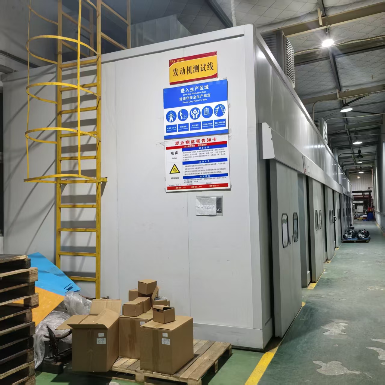
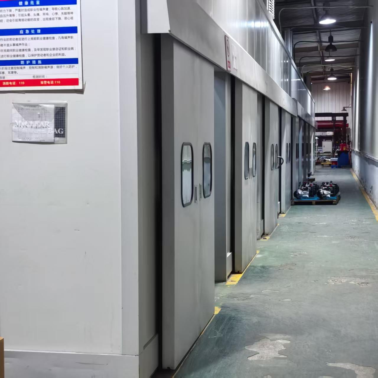
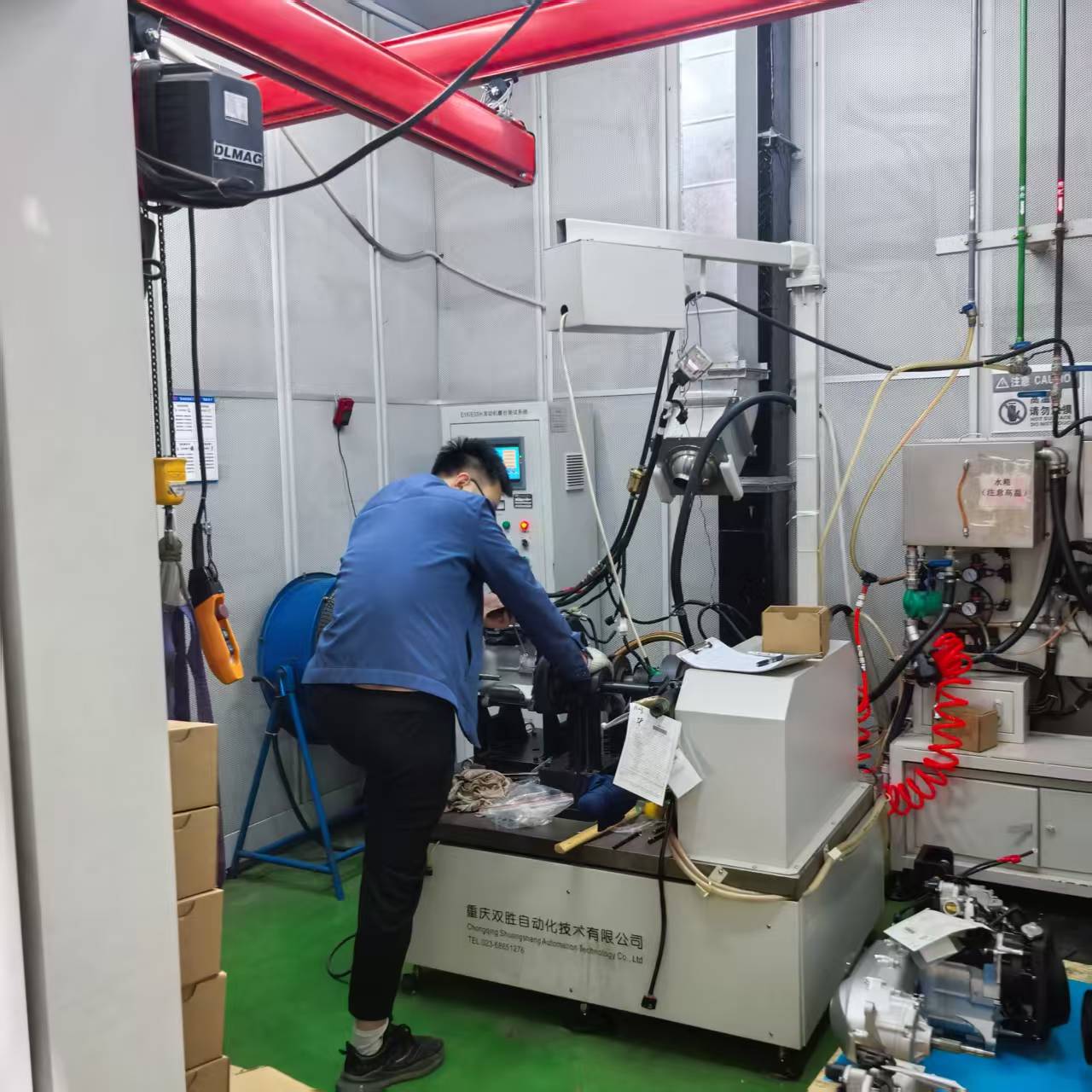
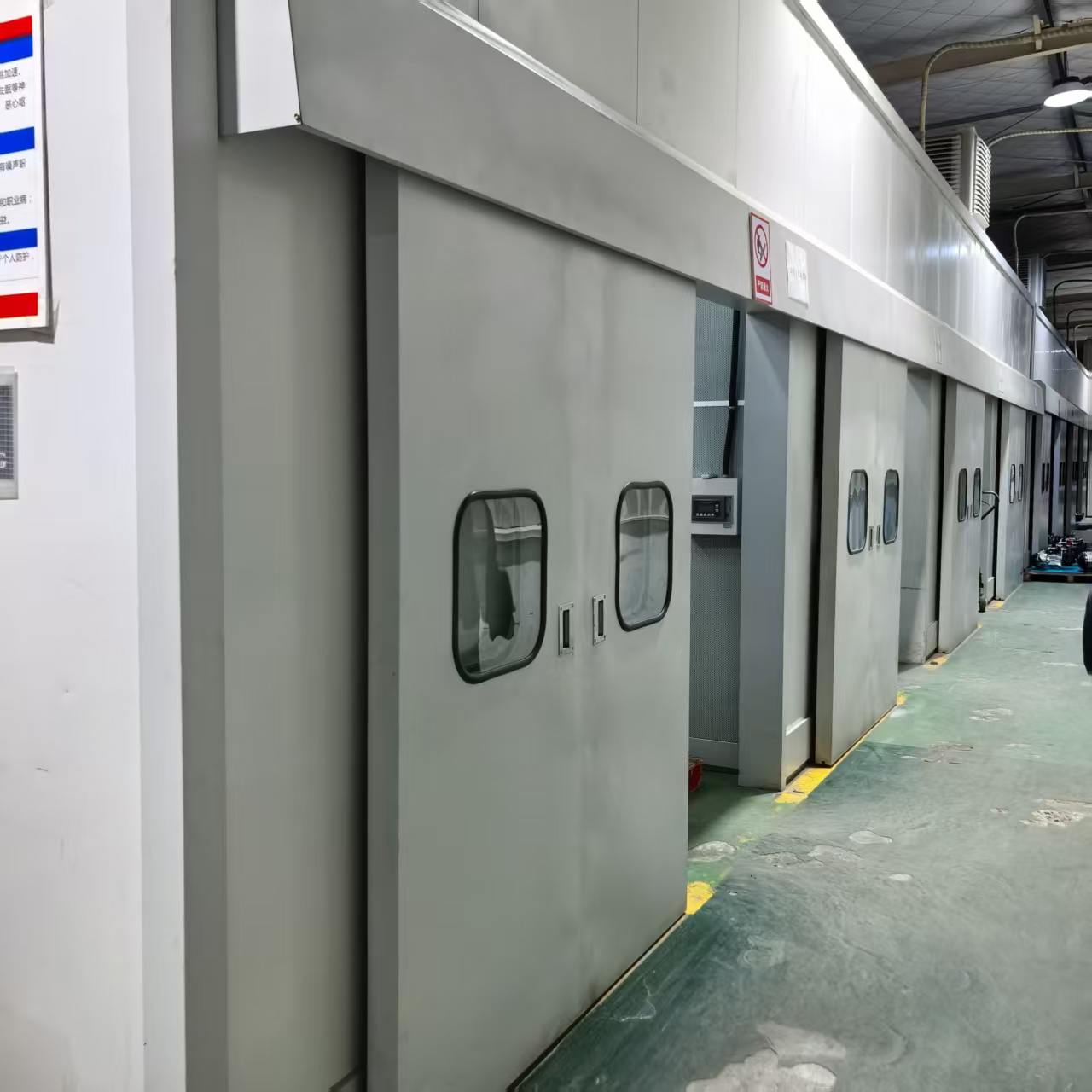
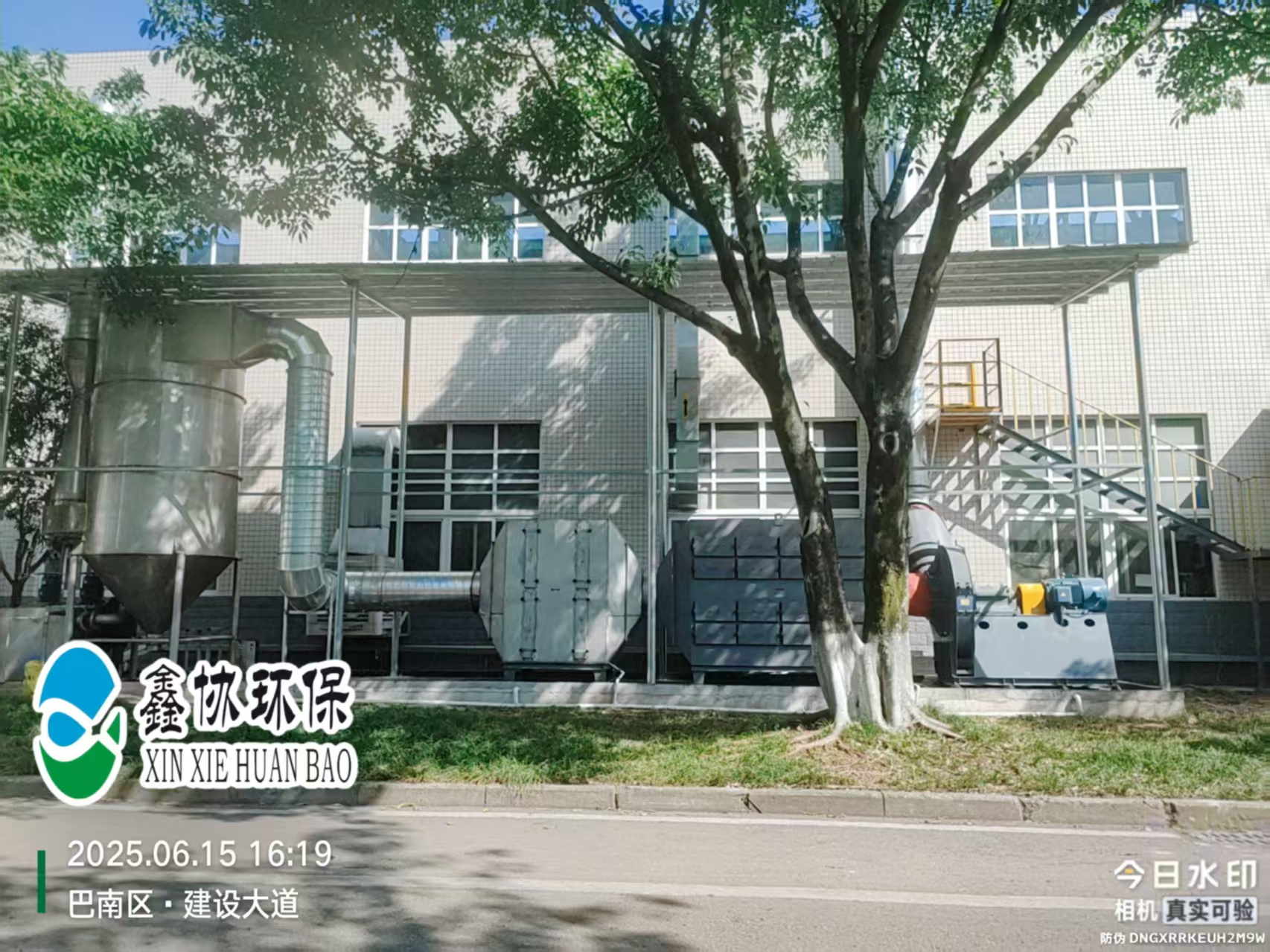
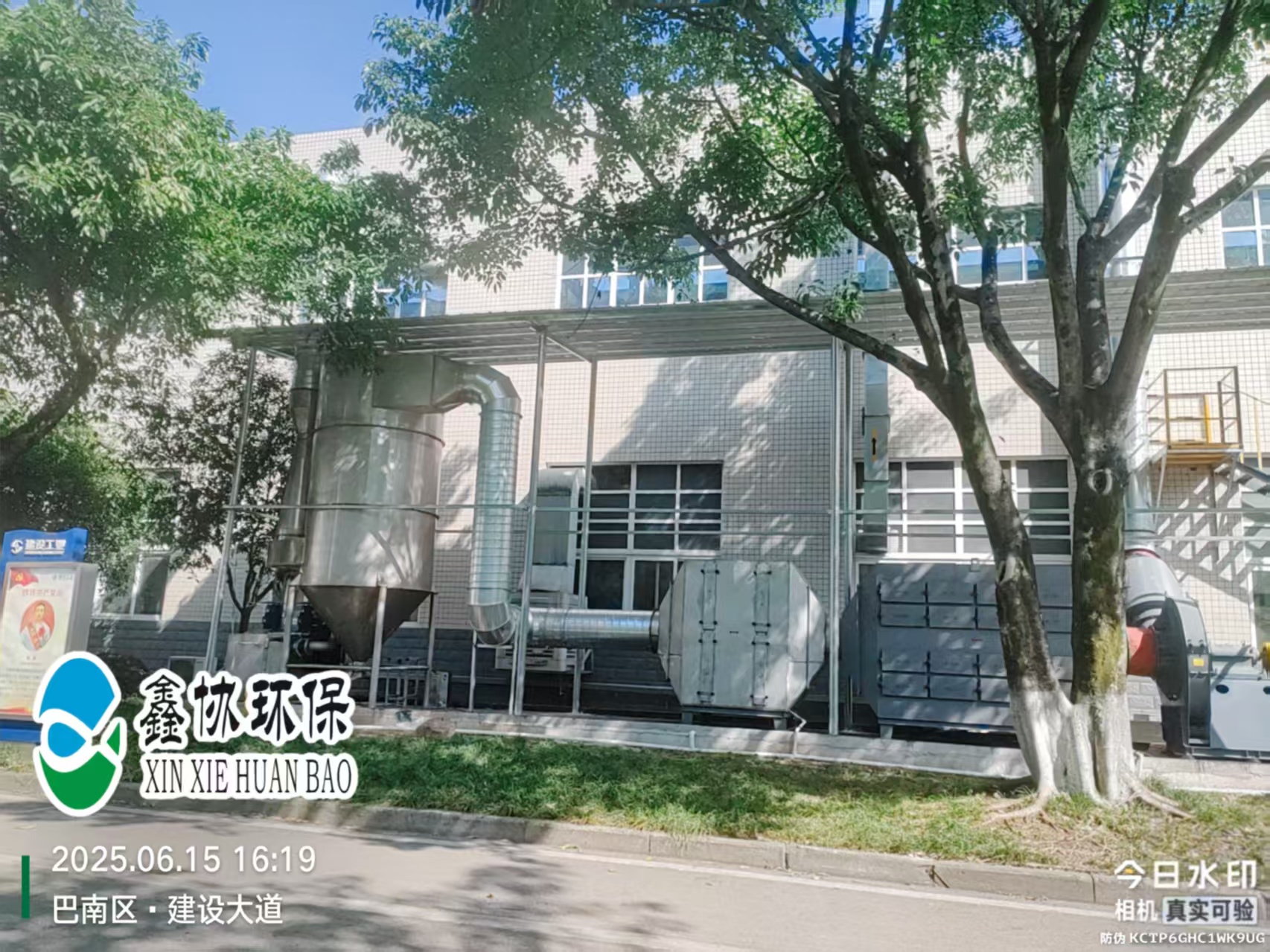
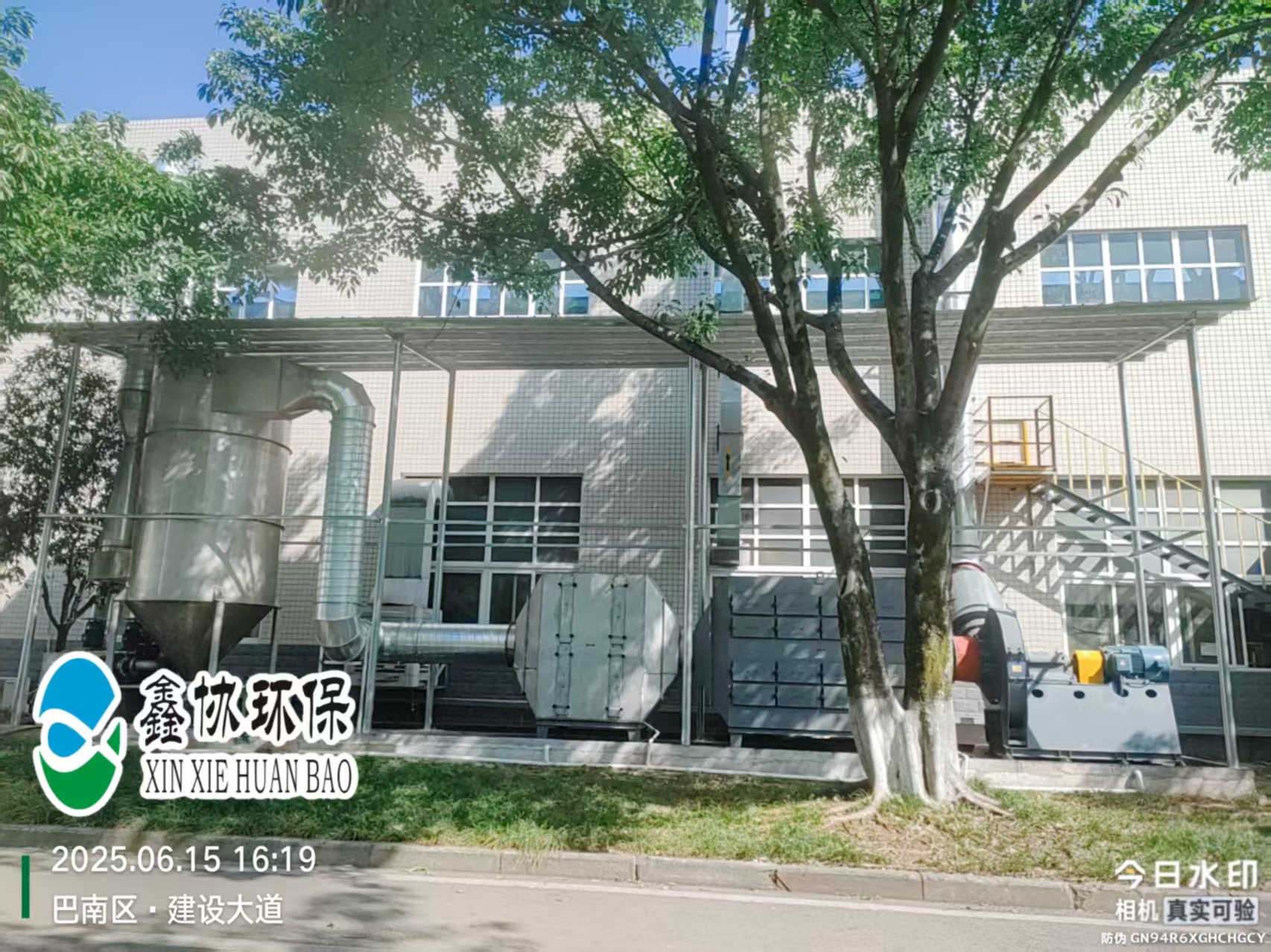
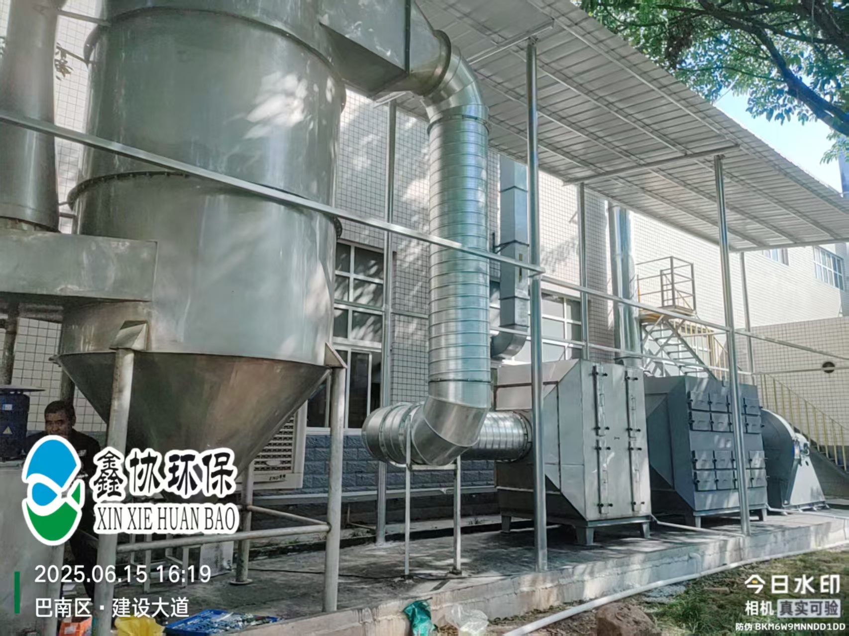
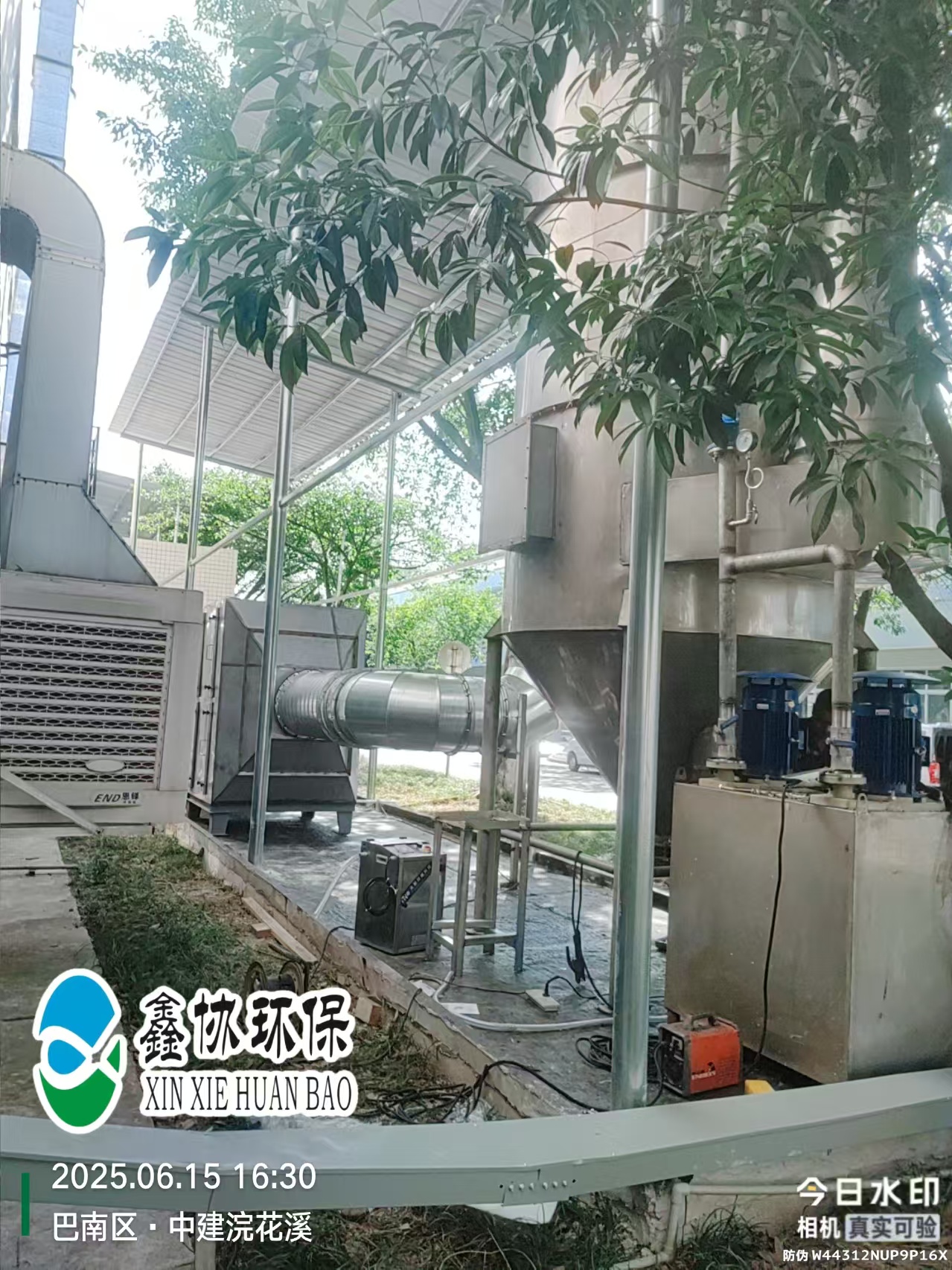
Reference photos of a completed organic waste gas system built by XinXie EP with the identical process sequence used in this project — swirl capture device, dry filtration and honeycomb activated carbon adsorbers, fan and stack — photographed at a client plant in Banan District, Chongqing (June 2025).
Noise, heat and tail-gas are one engineering problem — we solve it as one. Send us your room dimensions and test duty for a room-by-room air balance and a written proposal within 24 hours.
Discuss Your Project